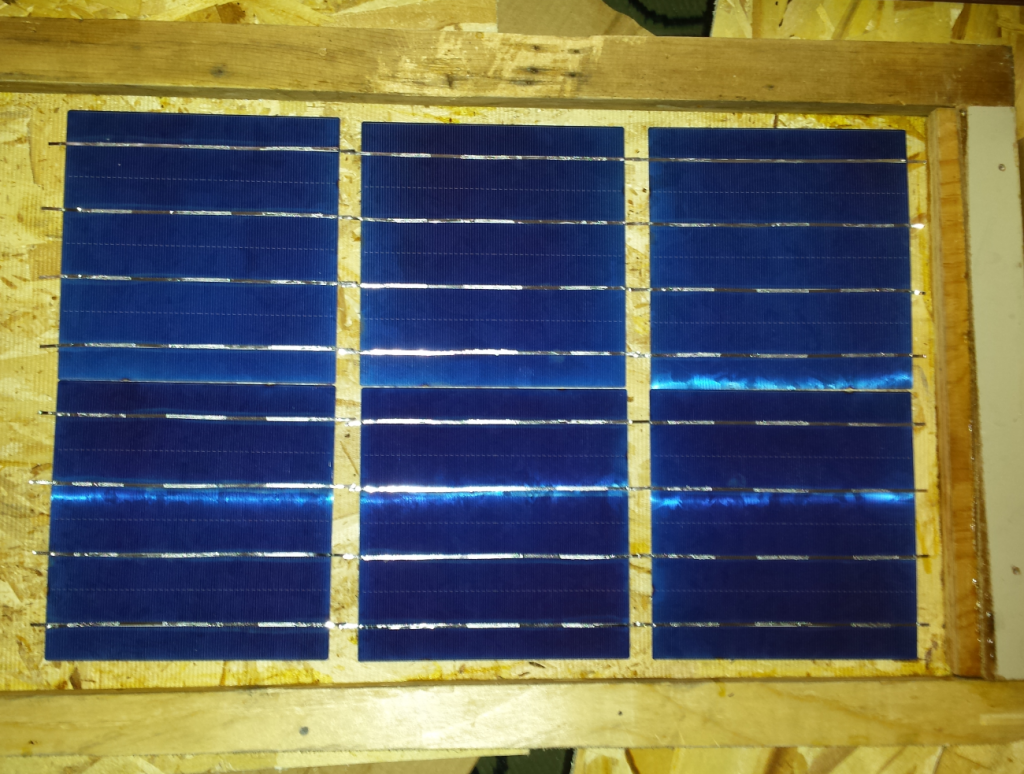
The cells are soldered in series to add their voltage and amperage. You have to choose a path that makes sense. In my case it’s simple, it’s a small window with space for 2×6 cells. With a larger window, you have to plan your shot to minimize the use of the bus (wide metal band) and get to the end with the right polarity. Be sure to place the cells so that the top of the first connects to the bottom of the next one.
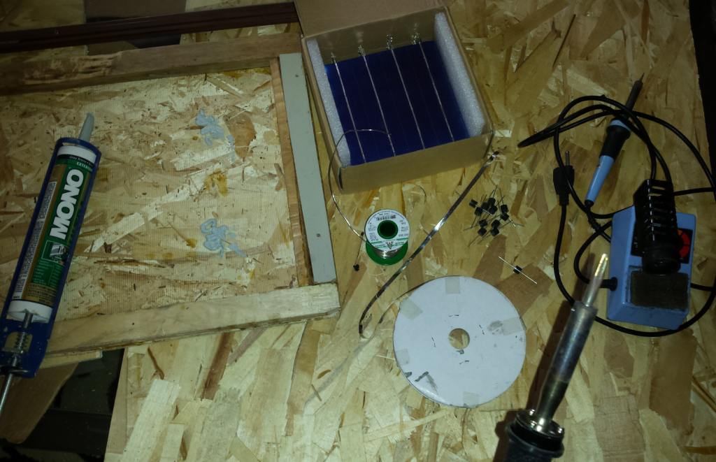
Here are the required materials:
- Silicon for outdoor
- Diodes 10 A; maybe 15 A or 20 are better, see details later
- Large metallic bus
- Soldering iron with flat head (the other soldering iron is not connected)
- Tin wire with fairly large diameter (it would be a waste of time to have a wire too thin because it must be put a lot)
- Multimeter; better buy a $ 50 and more with auto-range
- Pliers to draw the cable (is done differently, but it’s so much easier with the pliers)
- Quick grip or other weight to glue the pieces together
The idea is to put silicon only in the middle of the cell and not to put too much. Several sources say that under the effect of thermal expansion, the cells will change size and sticking them will help to prevent them from breaking. To this day, the panels I exposed to the elements withstood snow, frost, several rainy days in line and even a temperature of -35 degrees, they resisted well and no cells broke.
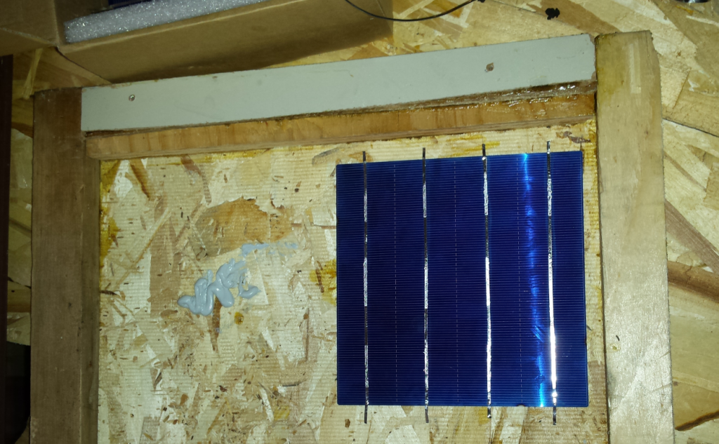
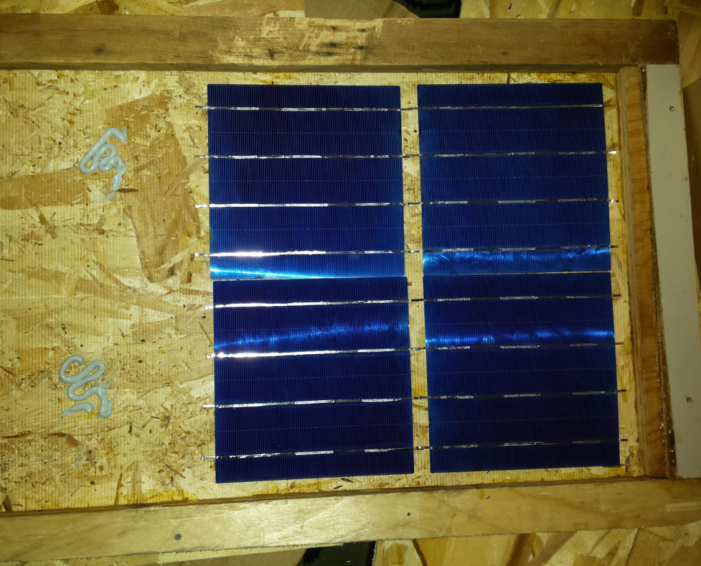
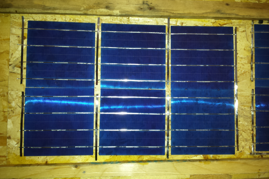
The first cell is stuck, there is still a little time to move it before it takes for good. You have to go with delicacy, otherwise the cell breaks in pieces. I leave some space on the sides for the additional circuit of the “bypass diode”. Note the side on the top that corresponds to the next cell below.
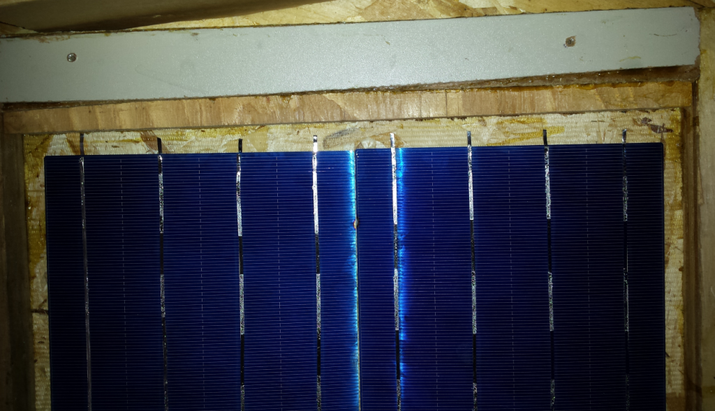
It is best to glue all the cells before starting to weld in order to avoid stress and breakage of cells.
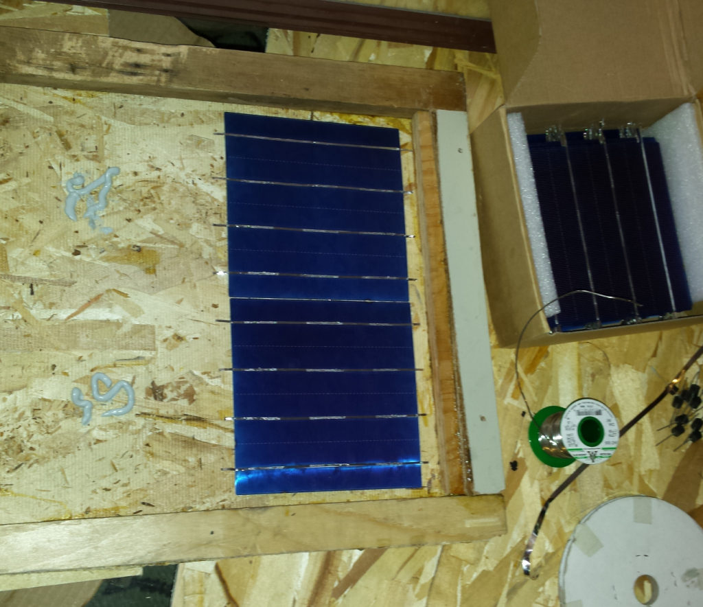
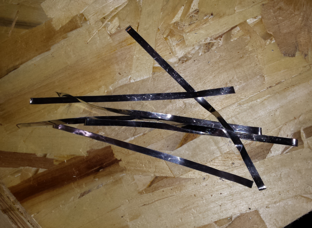
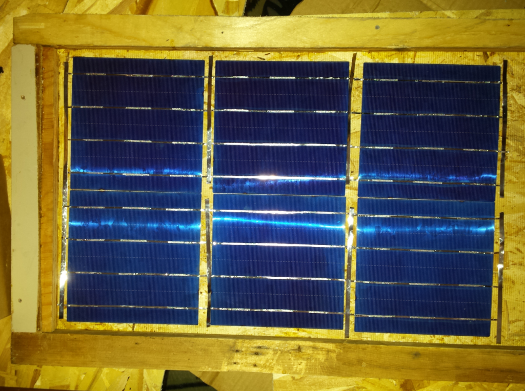
We cut 6 small and one long strips with the 10 A bus.
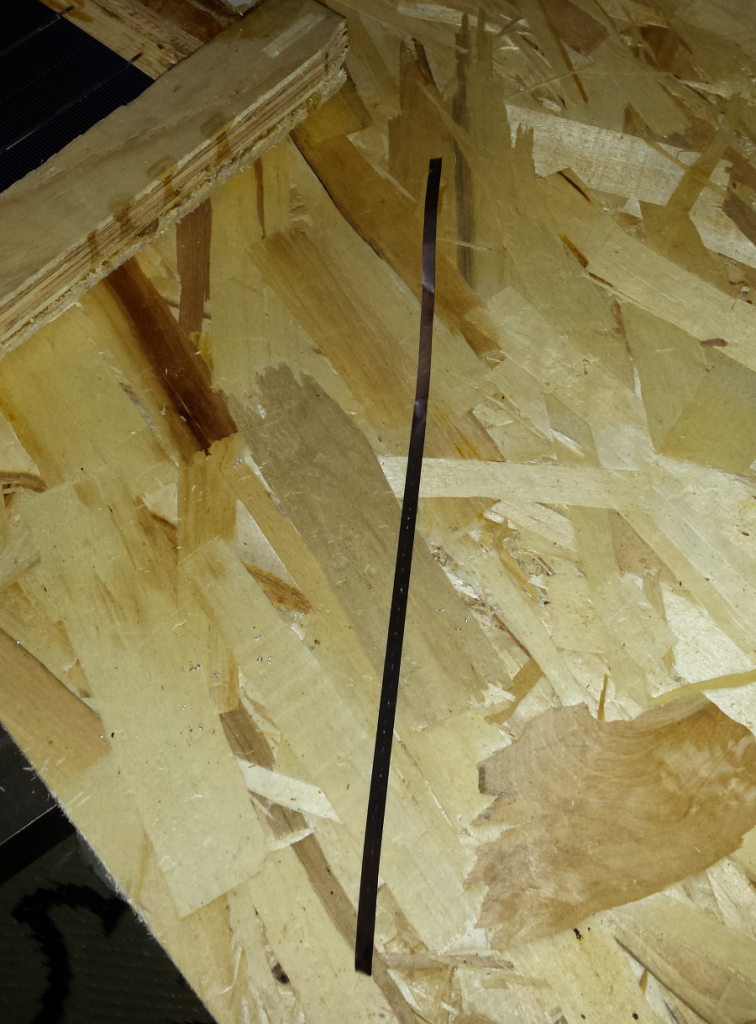
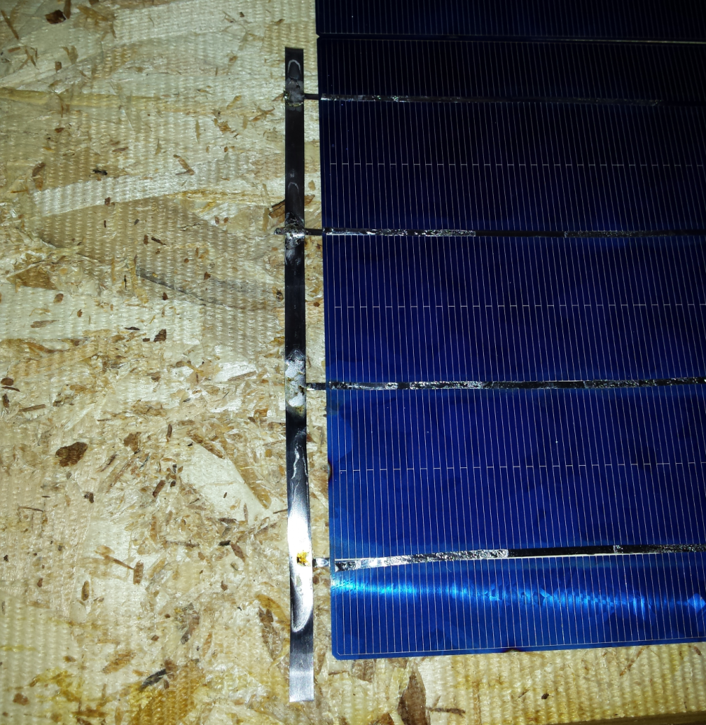
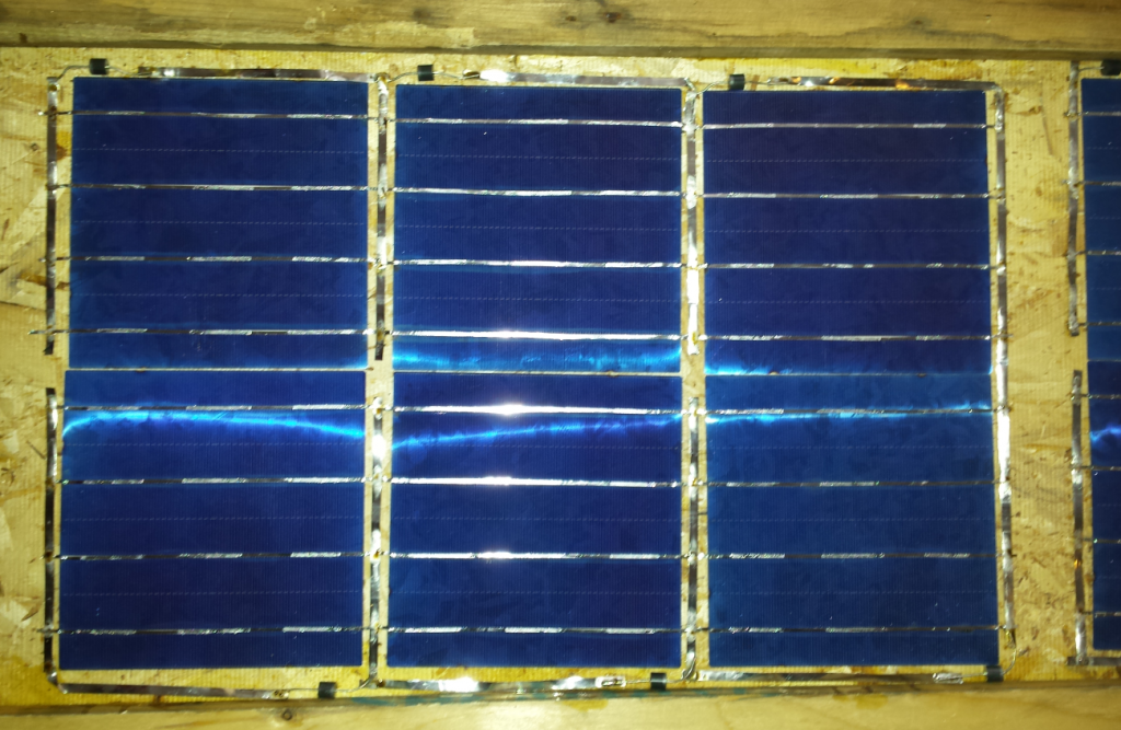
Here is the detail of the weld. Ideally, the resin should be removed from these welds to prevent oxidation. However, I admit that I had trouble putting alcohol on the cells without leaving any traces. I prefer to leave the resin and have the cells intact. At worst it will be possible to weld them again in a few years during maintenance, this is the idea of DIY!
All bands are welded. The soldering is repeated several times to be sure to have a very smooth and without stress solder (solder reflow), with the metal that sticks by itself to the surfaces because of the heat.
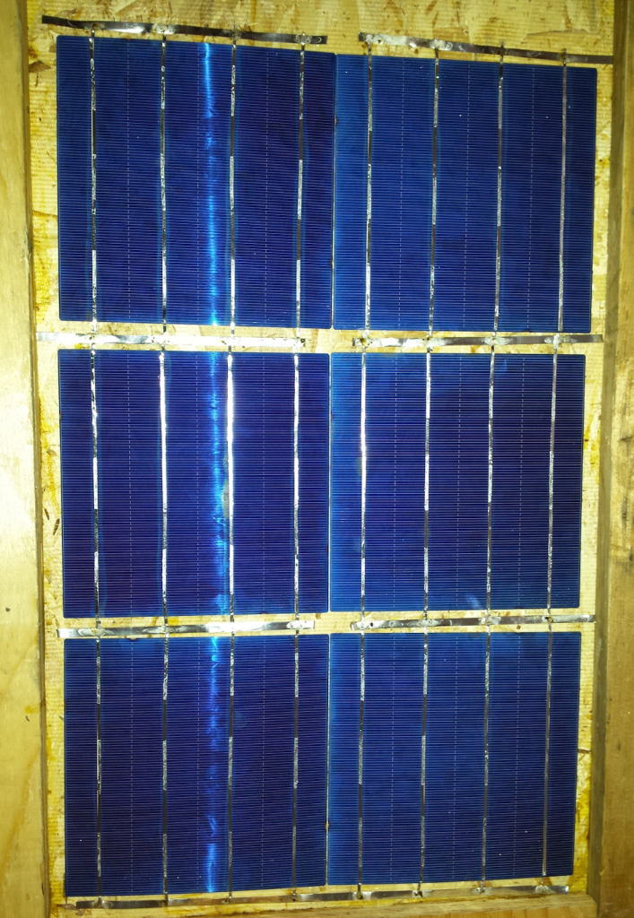
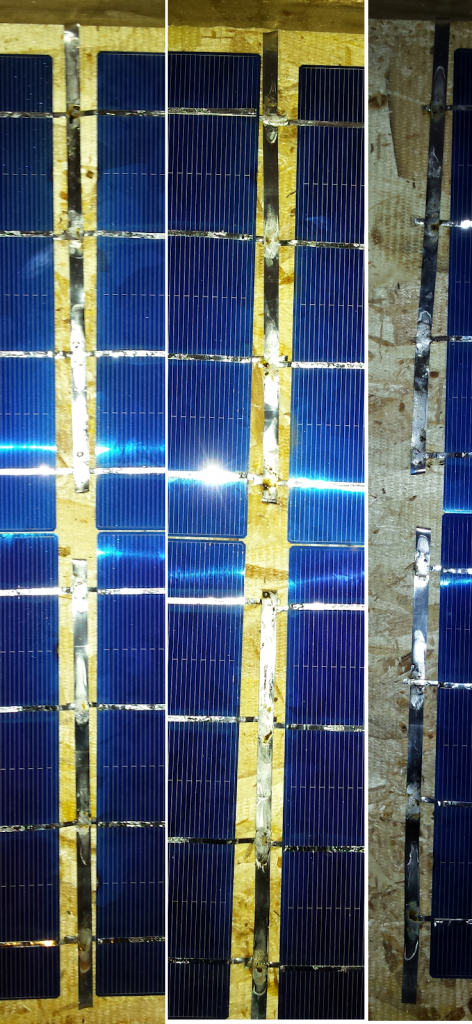
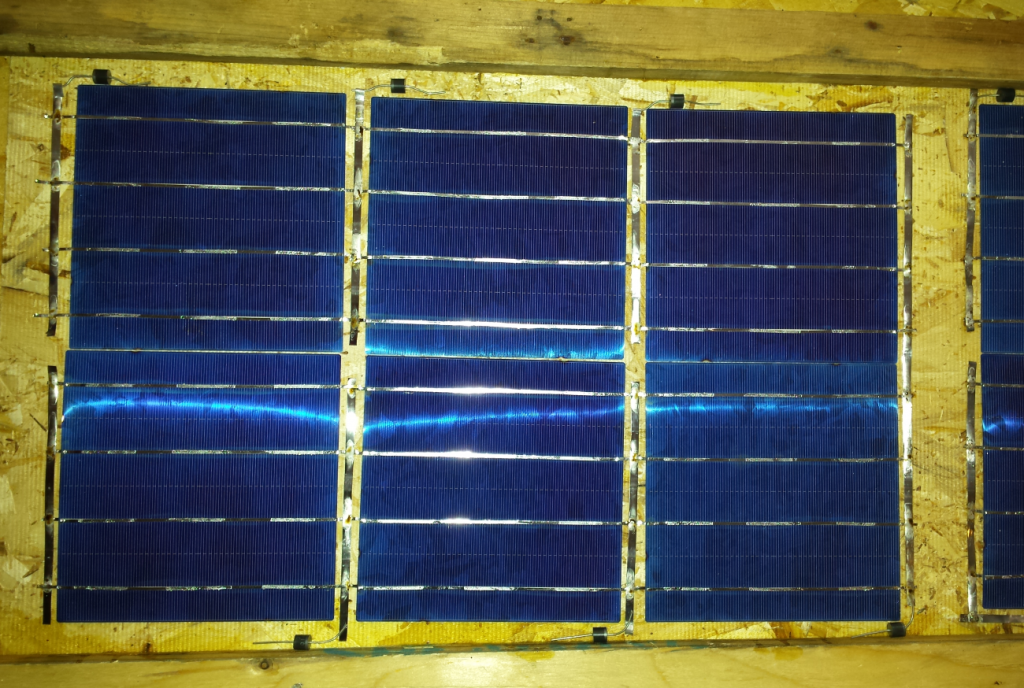
Now that everything is soldered, the diodes are placed by folding their legs. The negative side of the diode (the gray band) goes to the top of the cell (negative side).
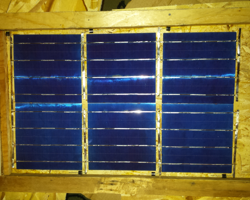
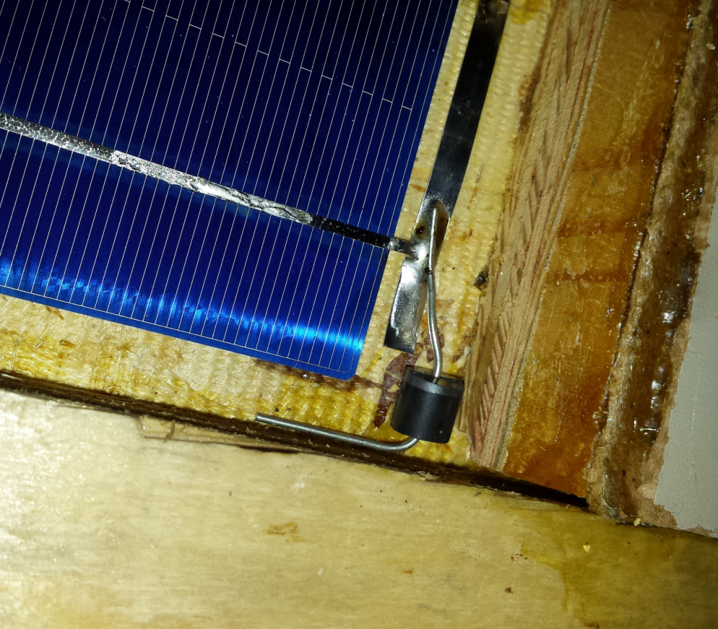
Other bus strips are cut to go around the cells and connect the diodes.
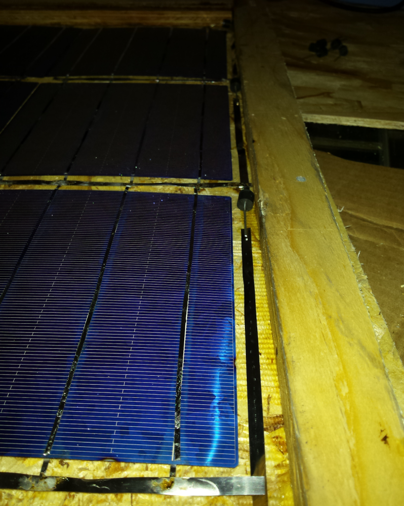
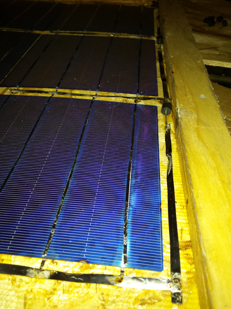
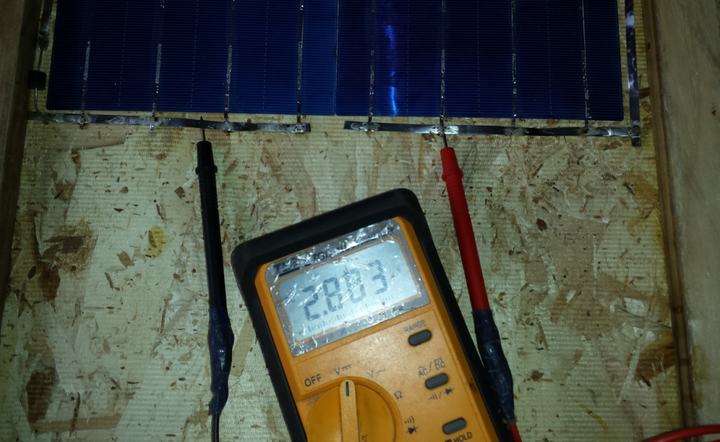
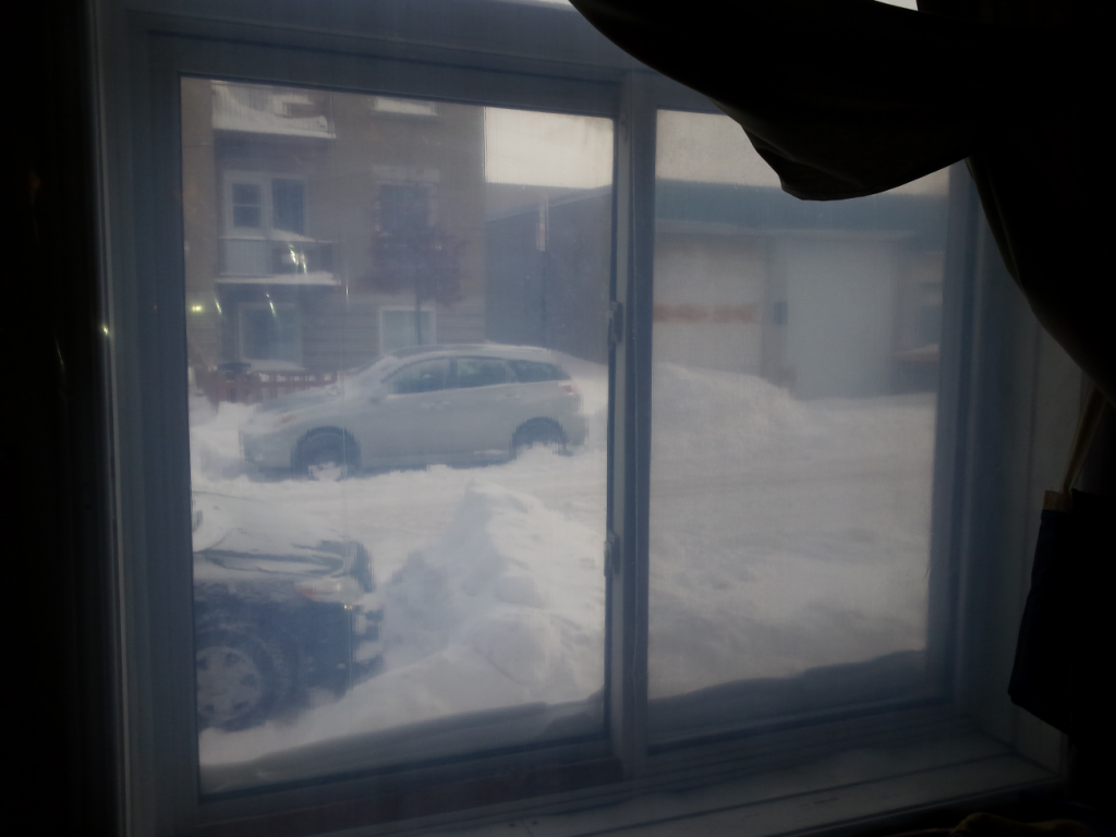
And There you go! Our 6 cells give 2.8 V in full winter storm, by the plastic of the window in the dim light. It is expected to have 3 to 3.6 V at a better place than in the living room. Moreover we see the voltage change with the flash of the camera!
In summary, there are 4 steps:
- Paste and arrange cells in series
- Weld the strips for the bypass diode and connect the cells to the ends
- Solder the diodes on one side
- Weld the other strips along the cells
It’s time to connect that to the outside world. Cable should be at least double the expected amperage. Here we have 30 A which is maybe a bit too much. If we connect 36 cells of 4.8 W, we have 172.8 W in total. In the big sun it gives 36 * 0.6 V = 21.6 V. We can now calculate the expected amperage in the best case, necessarily the panel will never produce 100% of its power because of many other factors. In addition, the use of “bypass diodes” will reduce the voltage in part; that said, it is very advantageous anyway because on average panels produce more if shade passes over cells or if a cell is damaged.
I like this tool to calculate the ratio watt-volts-amps (whatever it’s a breeze, a simple division): https://www.rapidtables.com/calc/electric/watt-volt-amp-calculator.html
That gives us 8 amps (172.8 W / 21.6 V = 8 A). I took 10A diodes but I should have used 15 or 20 A. To date it works well. You have to aim for double to reduce the risk of a diode breaking through wear, so 16 A ideally. Normally you want the double of the specification to make sure it will not overheat and maybe burn.
By applying tin to the end of the wire, it becomes very hot, we can then bend it and it will tend to keep this shape. Be careful not to burn yourself, use tools and do not touch with your hands …
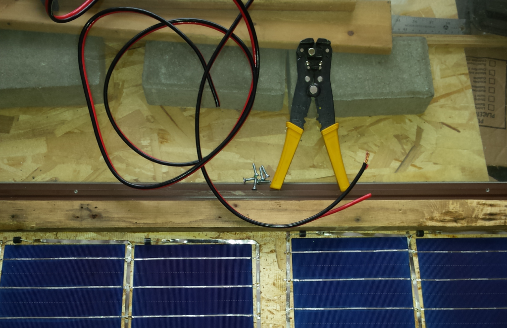
!!! Warning !!! In the photos that follow, the cables are connected backwards! Red and black should be reversed. This is an error I made on my first panel and I reproduce it by uniformity.
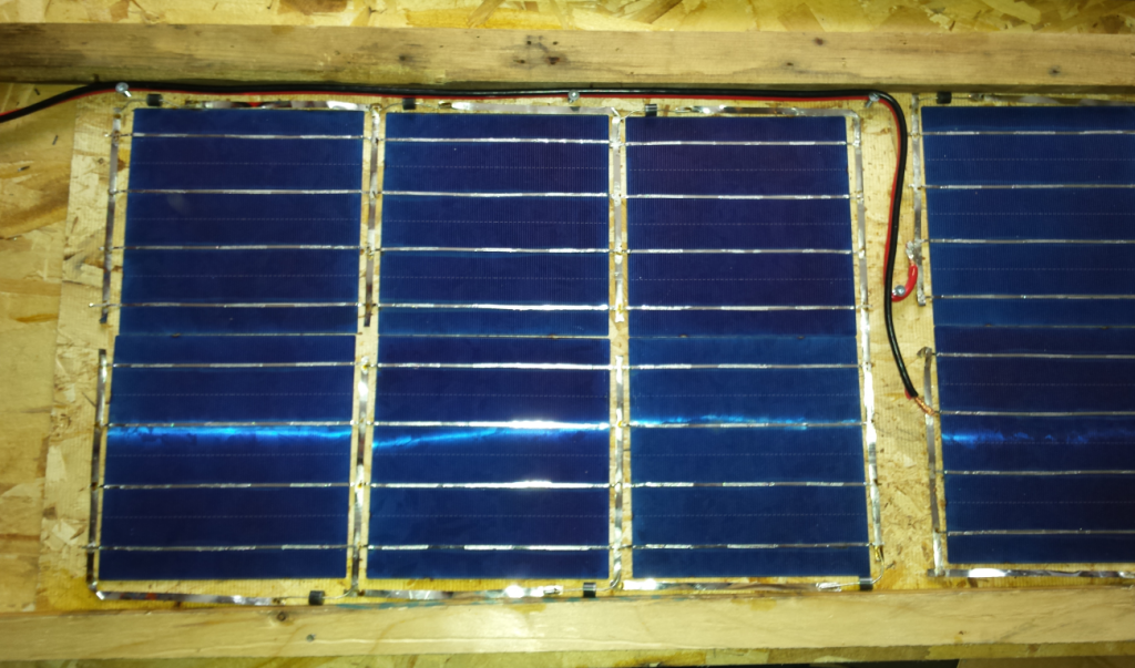
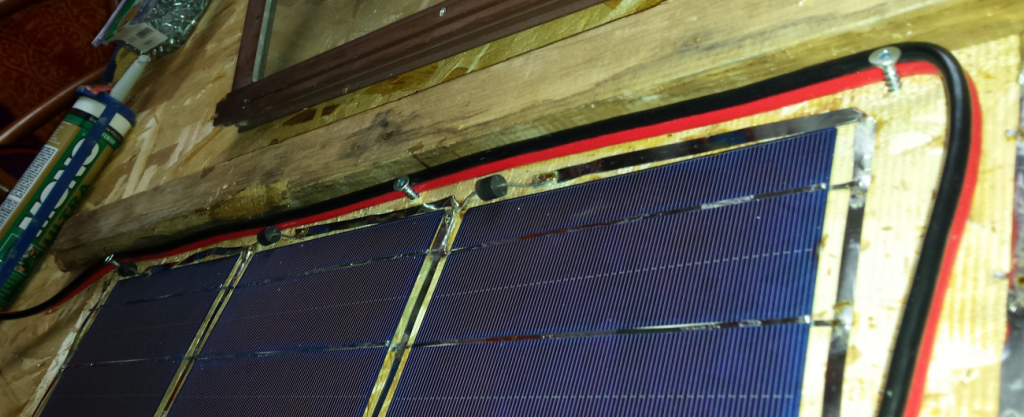
To reduce the stress of the cable on the weld and to prevent it from moving, which could break the cell, we put a screw where the cable is docked. Finally, we weld the wires on the bus at the beginning and the end of the series. I also put silicone to remove even more stress. Some screws should hold the cable in place. If you use a larger window, it is better to add a piece of wood in the middle to support the glass and to prevent a weight from crushing the circuit or putting it in contact with the water of condensation.
!!! Warning !!! The cables are welded upside down, you have to reverse the red and the black.
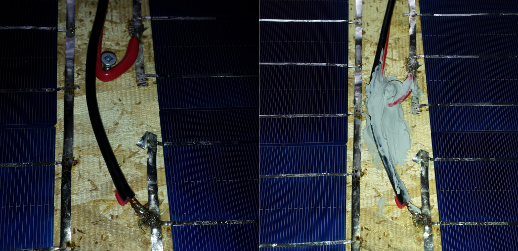
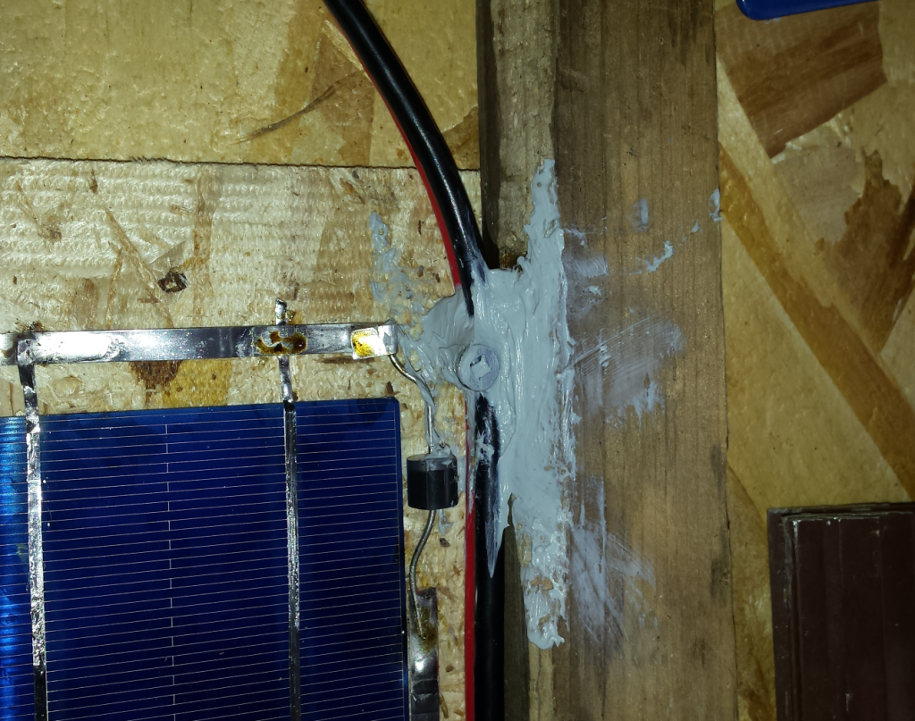
It also removes stress near the exit with more silicone because this is where the cable will move the most when connecting and disconnecting the panels. We must really prevent the movement to go to the cells otherwise it will break everything and lower the performance of the panel wasting our efforts and investments!
It’s time to finish the case and make the ventilation holes, away from water and bad weather.
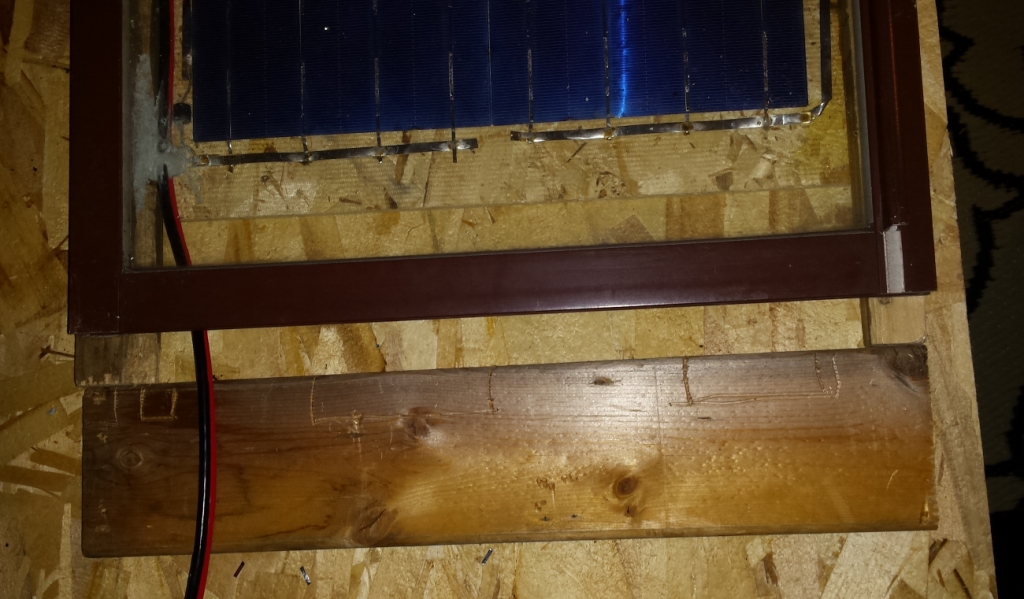
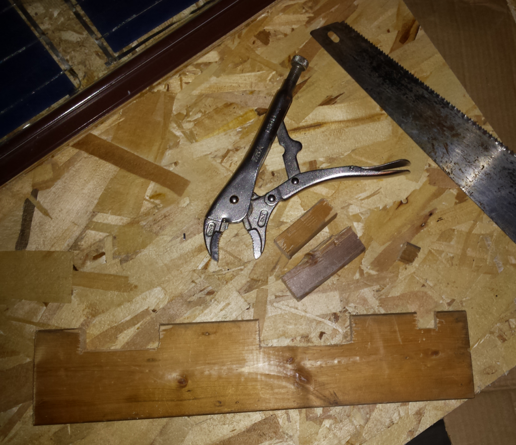
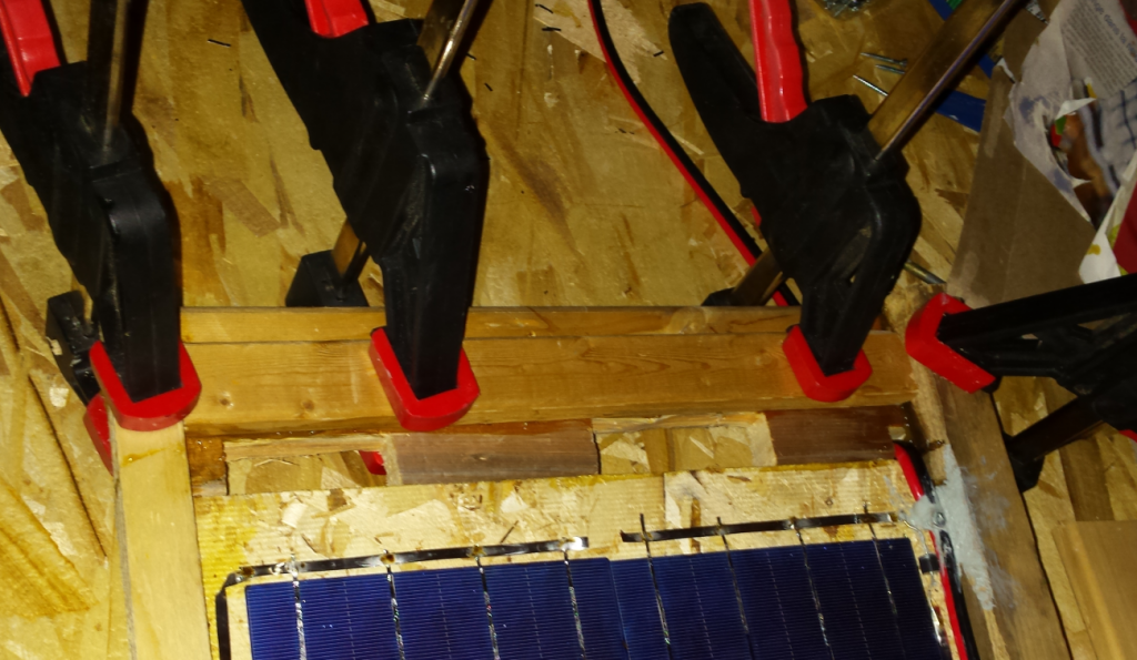
There are several ways to do it, here as the board below was cut too short, I add a piece of wood in which holes are added. With the pliers, you can pull the piece of wood prepared with the saw. We made two holes to promote the circulation of air.
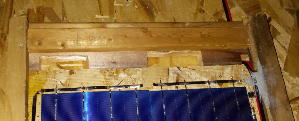
More glue … We can also make the air hole by sticking only a smaller piece between the glass and the base. The two holes being on each side of the piece smaller than the width, between the window and the bottom part instead of being on the outer surface.
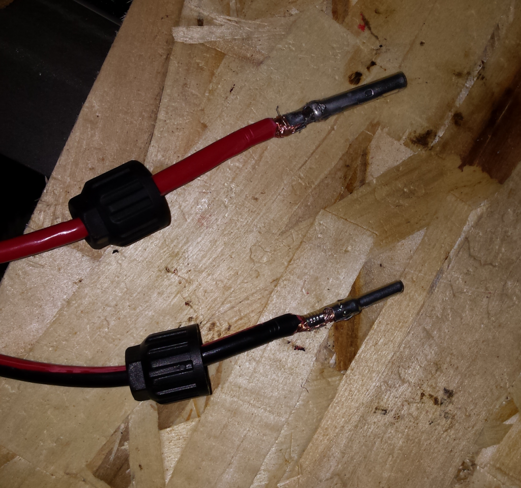
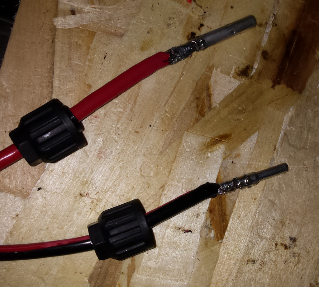
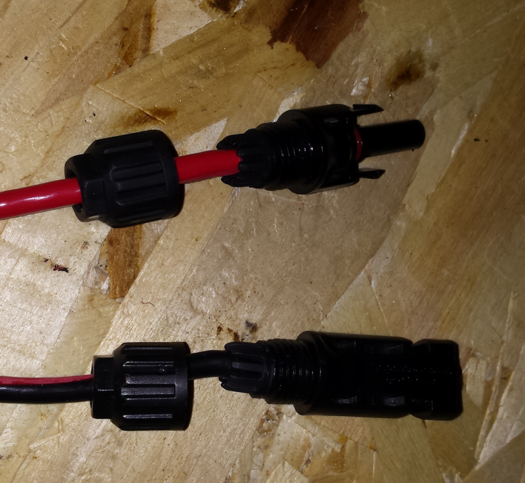
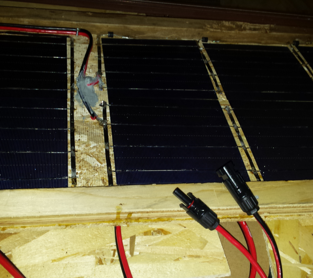
All that remains is to weld the MC4 connectors which are manufactured for the outside being very waterproof. The tin wire is coated to facilitate welding.
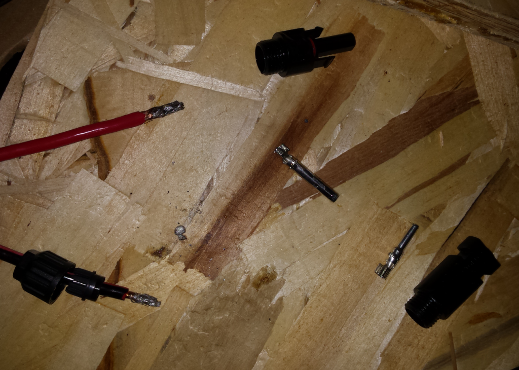
Before soldering, fold the end of the connector over the wire to obtain a cylinder. Then the interior is heated by injecting tin which should fill the inside of the connection. If the tin accumulates on the outside, it must be redistributed or removed because the connector will not fit well to the bottom of the piece of plastic, it must be perfect on the diameter of the cylinder.
